Sunday, March 25, 2012

Starter Motor's

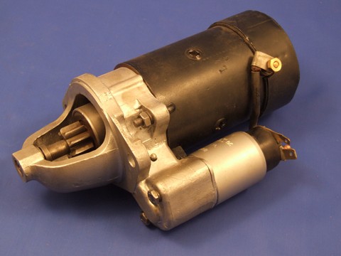
Starter Motor's are "STARTER" Motor's. They are motors that start the big motor. Enough of the jokes, yes Pat, if you're reading this I am that bored. OK, business time. When the starter switch is operated the solenoid becomes activated and the plunger us drawn in to the core by electromagnetism. This action engages the the pinion in the flywheel ring gear. At the same time the other end of the plunger the solenoid contacts move backward and creates a high current circuit which can be used to the spin the armature, through the brushes and the commutator. The pinion is connected directly to the armature and spins when the armature spins, cranking the engine. After the engine has been started, the pinion speed will exceed the starter speed. If the the starter is still in use this one way clutch will release allowing the drive to freely spin thus protecting the motor from over speeding.

There are two common types of starter motor that may be found in modern day small vehicles:

1) Pre Engaged Starter Motor:
    Basically all the writing above.
 
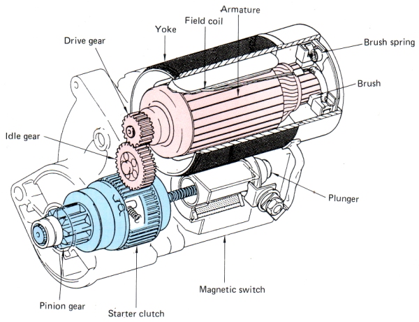
2) Gear reduction Starter Motor:
    Much like the pre-engaged, but is noticeably
    lighter and produces higher torque. The armature
    is located on top (where the solenoid is on the
   pre-engaged), and the pinion is moved into mesh
   by a plunger where the armature is on the
   pre-engaged (displayed in the image below)


There is a third common type around, inertia type. I didn't include it above because it is not used in modern cars, but it is being used in cars that may be still operating in older vehicles on the road today. The main difference in a inertia type is that there is no plunger or solenoid that will move the pinion into mesh with the ring gear. This is however achieved by the armatures initial movement. The force of the armature movement moves the pinion in the opposite direction to the above starter type.


Alternators

An alternator is a main component of a vehicles charging system. It does this by converting alternating current (AC) into direct current (DC) which can be then received by the battery. An alternator is an electromagnet that is driven off of engine power through the pulleys.

The picture above shows an alternator in its full glory. The black thingy on the side, that would be the pulley and the driving force of the alternator.

To be quick, and simple about it to avoid mucking my thoughts up.  Electron current is induced when the Rotor spins inside the stator. The Rotor receives its current through a pair of slip rings attached to the rotor shaft. The current is passed on from the voltage regulator through a pair of brushes which come in and out of contact of the slip rings while they are rotating. The stator is a group of conductors that pass alternating current into the rectifier where it becomes a direct current which can be then absorbs by the batterey. The stator itself is a group of conductors that induce current as the rotor's electromagnetic field cuts across the conductors. As the electromagnetic field is both positive and negative current is produced in two differing directions which can not be sent to the battery(+) as is.

Above:  A typical alternator circuit.

Sunday, March 11, 2012

Basic components

This week i can't say that i have much to report on as I have been absent from two of my four lessons in the past week as of the business with my mom travelling out of the country and the loss of my uncle. From what I did pick up last week is that we learnt about diodes and relays.

    A diode, to my general understanding, is a component that allows current flow in one direction but not in the other e.g. allows current flow from the positive to negative terminals, but not from negative to positive. A diode can be either a consumer (e.g. a LED) or not. Its purpose is to ensure current flows in a desired direction within a circuit. Ofcourse there are many types of diodes but due to my inability to wake up in time to wake up early enough to attend the lecture i am not able to report on the design and functionality of the other types of diodes.


   A relay is a tad more complex than the diode and I warn any that may read this that my the following shouldn't be anything to go by. My general understanding of a relay is that it is a switch that consists of a electromagnet and several contact points as shown in the picture to the left. In the picture it shows an open switch (which is in parallel) which means that the no components in the circuit will be powered. If one were to flip the switch, then the electrons would the flow to the control coil which would produce an electromagnetic field within the iron core, which would in turn pull the the two contact points together and let electron flow to the load (component) at the other end of the circuit. When the switch is flipped again the electromagnetic field collapses and the connection between the contacts is broken, cutting of the flow through that circuit. More often than not there is a spring that would return the contacts back into their original position.


A Transistor is basically a rapid switching relay.


 "The essential usefulness of a transistor comes from its ability to use a small signal applied between one pair of its terminals to control a much larger signal at another pair of terminals" as shown the diagram below. This transistor is positively connected, meaning that the transistor is controlling the positive side of the circuit. The base is the wire which connects and disconnects the current flow between the emitter and the collector. 

A transistor may be used instead of a relay because:

No moving parts
Requires no maintenance
Switching is silent & instantaneous
Not affected by vibration


Sunday, March 4, 2012

Electricity and Circuit basics

Over the past week we started our Auto Electrical & Electronics section of our course this year. Over the past week we have been learning the basics of electricity through classroom and practical sessions. We learnt the terms and their purpose within a circuit.

Terms:


Voltage = "Practical unit of electromotive force". The way i would I understand voltage is a force that pushes electrons through a conductor. The "pushing force" if I may use the simplest of english.

Ampere = "Unit of current". I wouldn't hesitate to point out that i struggle to describe ampere in simple english. Referring back to my book "the larger the amount of and flow of electrons the larger the current". I would say Amp's are a measurement relative to the amount of electrons (electricity) flowing through a circuit, but to anyone who may read this in the future, i may be completely wrong so i wouldn't trust  what i say. 


Ohms = "Unit of resistance". Resistance refers to the blockage or slowing down of electron flow through a circuit. Resistance comes in various forms but the one we were shown and worked with was a light bulb. 


Wattage = "Work being done". To me Wattage is the measurement of energy used to power a circuit and its components. 


There are a lot more terms that i should be describing but because of my being absent to most of my classes in the past week.

Circuits:

Circuits are a path which electrons can flow through, from a positive to negative outlet (usually a battery). A basic circuit, to my understanding, consists of a fuse, a resistor, a power source. I say to my understanding because i do believe some countries define it differently.  The circuits we used were basic, but changed the amount of resistors or configurations depending on the task. We used and researched series and parallel circuits.

Series circuit = A circuit where all the components (resistors (light bulbs)) will share a common positive lead and earth.

Parallel circuit = A circuit where each resistor (light bulb) would have its own positive lead and ground.

Compound circuit = Where both circuit configurations are apparent. A parallel circuit and series circuit in one.

With these we were to find out the repercussions of adding or taking away a resistor from the system.
   E.g;
        :Adding a light bulb to the series circuit dimmed the bulbs across the board and slowed the current because the available 12v had to be shared with another bulb, and the new bulb added resistance slowing the current.
       :Adding a light bulb to the parallel circuit did not affect the brightness of the bulbs because each bulb was receiving the full 12v, and the current increased throughout the entire circuit because there was an overall less resistance in the circuit.

Unfortunately I do not have any photo's or my worksheet so i could further elaborate on the preceding passages and I will begin to take pictures as soon as I can locate a camera.